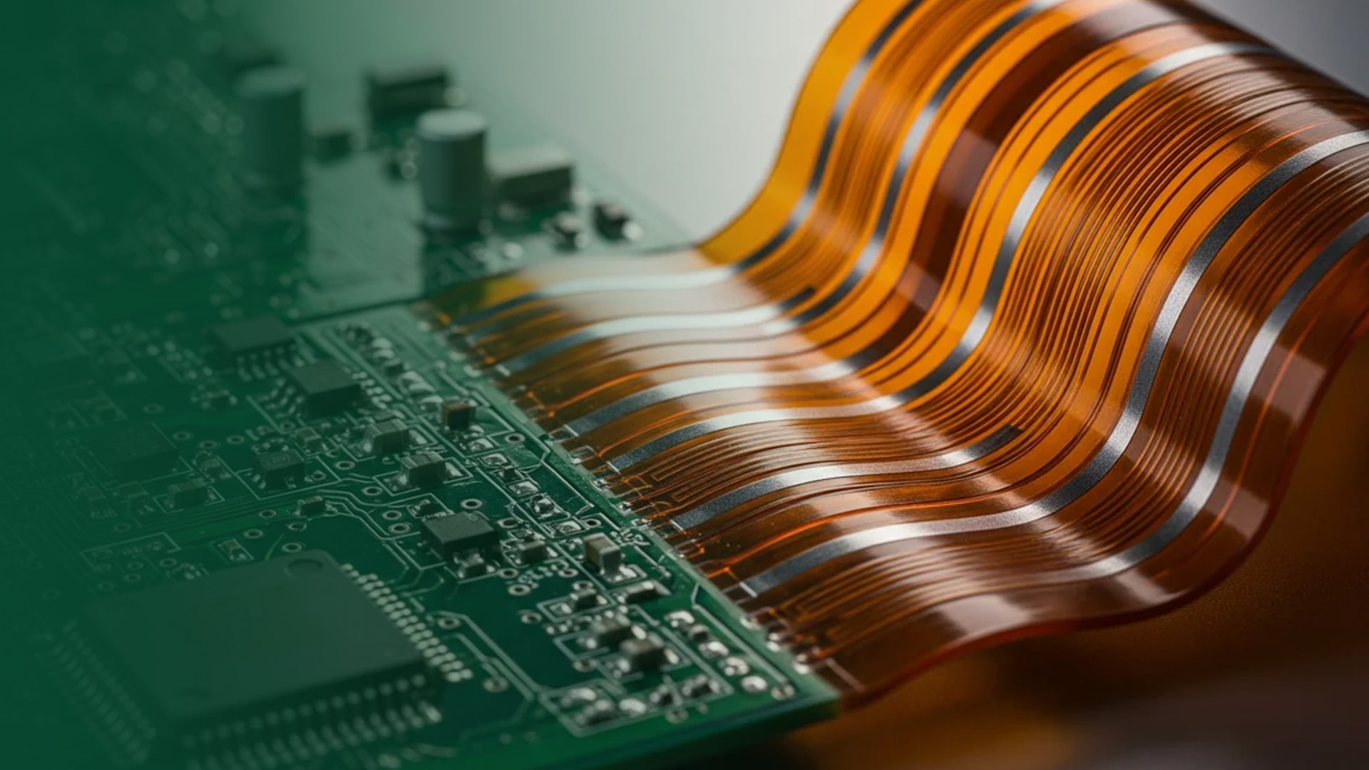
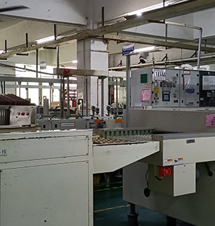
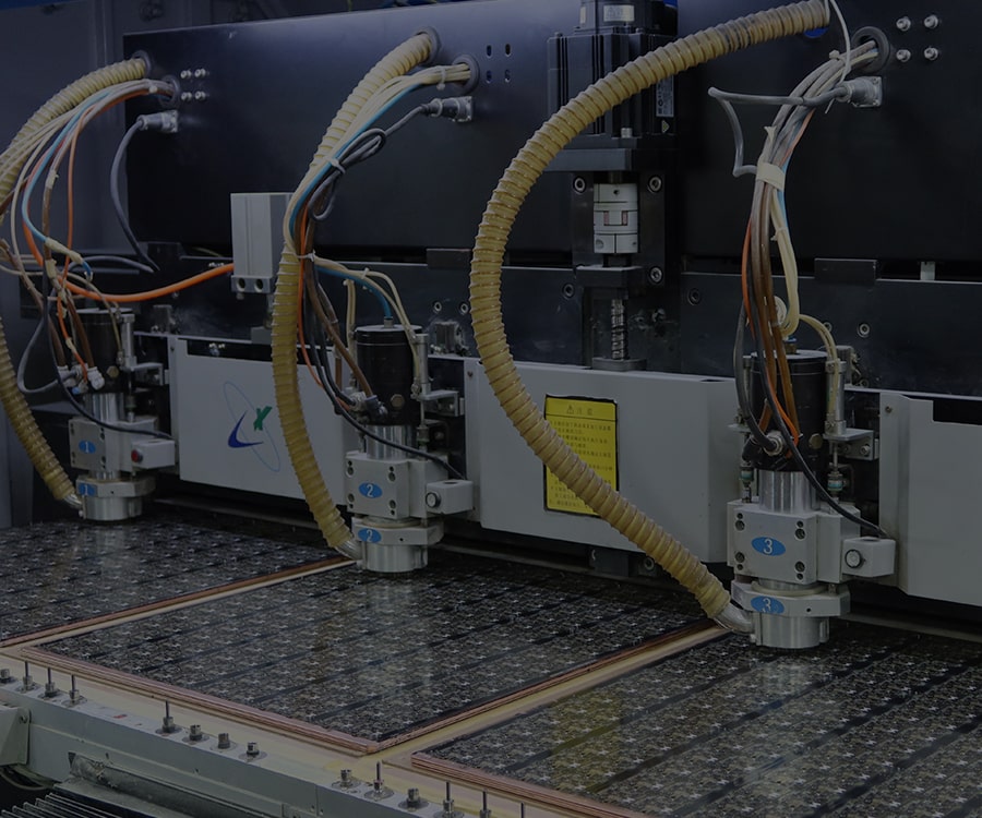
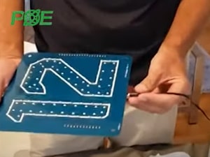
POE focuses on the fabrication of bare flexible printed circuit boards (FPCs) for rapid prototyping and volume production. We process PI and PET-based flex cores with RA or ED copper, delivering stable roll-to-roll consistency and tight dimensional control for dynamic bend applications.
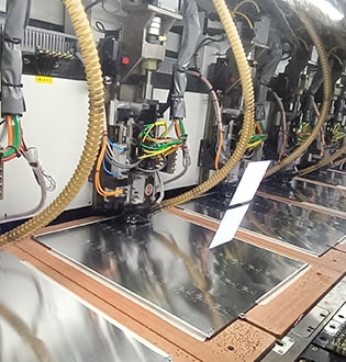
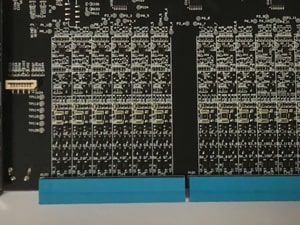
Our dedicated flex lines support precision etching, micro drilling/laser vias, coverlay application, and surface finish for bare FPCs ready for downstream assembly. From thin single-layer jumpers to multilayer flex with impedance control, we build to your design intent and reliability targets.
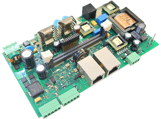
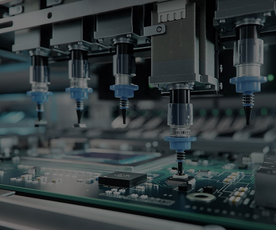
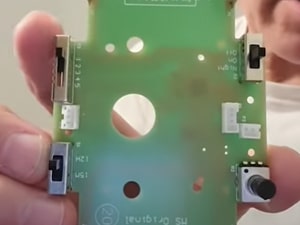
Bare flexible PCBs enable ultra-thin, lightweight, and highly bendable interconnects for compact devices. Provide your Gerber and stack-up intent, and POE fabricates stable bare flex circuits with consistent copper uniformity and excellent bend fatigue performance. Ideal for dynamic flexing, tight enclosures, and weight-sensitive designs.


POE’s bare flex manufacturing complies with ISO9001, ISO14001, ISO13485 and RoHS/REACH requirements. UL and IPC standards are followed to ensure traceability, safety, and consistent quality across prototypes and mass runs.

ISO9001

ISO14001

ISO13485

REACH

IPC

SGS

RoHS


Global logistics (expedited options available)
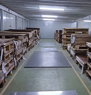
Bare FPCs are moisture-controlled and protected with ESD packaging, cushioned with bubble wrap, and boxed for international transit. We support vacuum sealing and reel/roll packing as requested to fit your assembly workflow and storage conditions.
Send Gerber and stack-up to
all@poe-pcba.com
Receive a tailored quote
within 24 hours
PO confirmed and
schedule locked
DFM and EQ for bare flex;
final CAM approval
Start fabrication;
typ. 2–4 days
Scale to volume
1–15 days by qty
Door-to-door
worldwide shipping
Feedback welcomed;
after-sales available
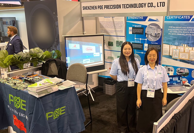
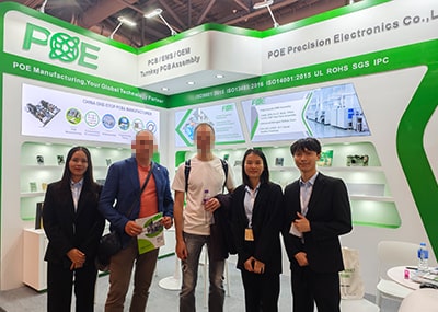
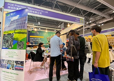
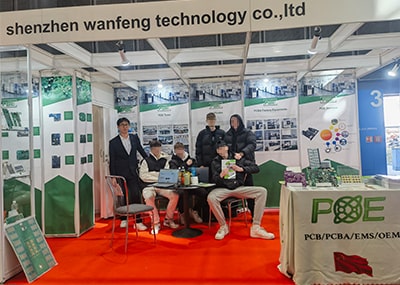
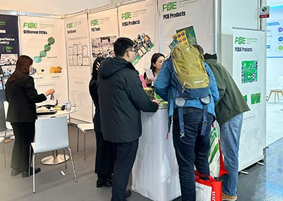
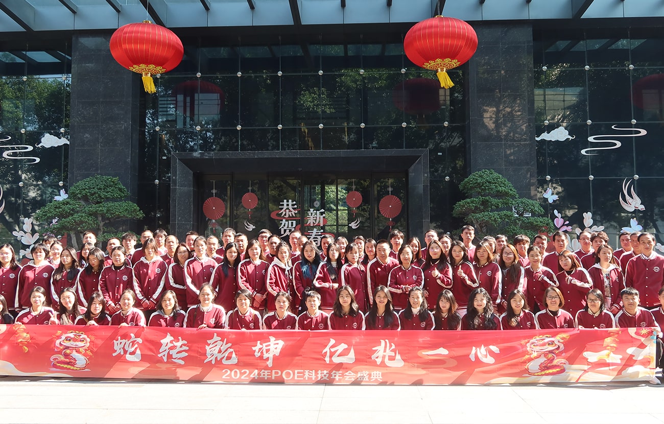
Meet POE at global electronics exhibitions to learn how bare flexible circuits can reduce weight, improve reliability in dynamic movements, and simplify assembly in space-constrained products. Ask our team for live samples and capability charts.
Recent Bare Flex Orders
| User Name | Date | QTY | Price |
|---|
Excellent bare flex quality with tight tolerances. Quick prototype turnaround!
Customer from the Canada
Professional support for PI and PET constructions. Very satisfied.
Customer from Australia
Consistent copper thickness and great bend reliability.
Customer from USA
Impressive microvia quality and clean etching for fine lines.
Customer from Australia
Great communication and on-time delivery for our flex project.
Customer from USA
Reliable flex supplier with solid process control.
Customer from UK
NEWS & INSIGHTS
Design Tips for Bare Flex: Bend Radius & Trace Routing
Learn how to select proper bend radii, staggered traces, and copper balancing techniques to maximize flex life and avoid cracking in dynamic applications.
2025/1/12

PI vs. PET: Choosing the Right Flex Base
Compare mechanical endurance, temperature limits, and cost to pick the optimal material system for your bare FPC design.
2024/12/25

Surface Finishes for Bare Flex
When to use ENIG, OSP, or hard gold pads on bare flexible circuits to balance solderability and cost.
2024/11/11
REQUEST A FREE CONSULATION
Tell us your bare flex requirements (layers, material, thickness, finish, impedance). Upload Gerber/stack-up and we’ll quote immediately.
For any quality concerns on delivered bare flex:
We offer 24/7 after-sales support.
NDA available on request before file transfer for full confidentiality.
 Email: all@poe-pcba.com
 Whatsapp: 85292069596
 Tel: 0755-25312250/ +8613798543496
 Factory Address: Floor 3, Jinyuan Industrial Park, No. 56, Tangtou Avenue, Shiyan Town, Baoan District, Shenzhen China