Web Analytics Made Easy - Statcounter
Flex PCB with Controlled Impedance
This website uses cookies:
Our website use cookies to analyze website accesses and improve your online experience. By continuing browsing this website,you agree to our use of cookies and privacy policy.
Accept all cookies
Decline
This website uses cookies:
Our website use cookies to analyze website accesses and improve your online experience. By continuing browsing this website,you agree to our use of cookies and privacy policy.
Accept all cookies
Decline
Get A Quote
Get A Quote
Flex PCB with Controlled Impedance
21 August 2026
Views: 103

Flex PCB with Controlled Impedance


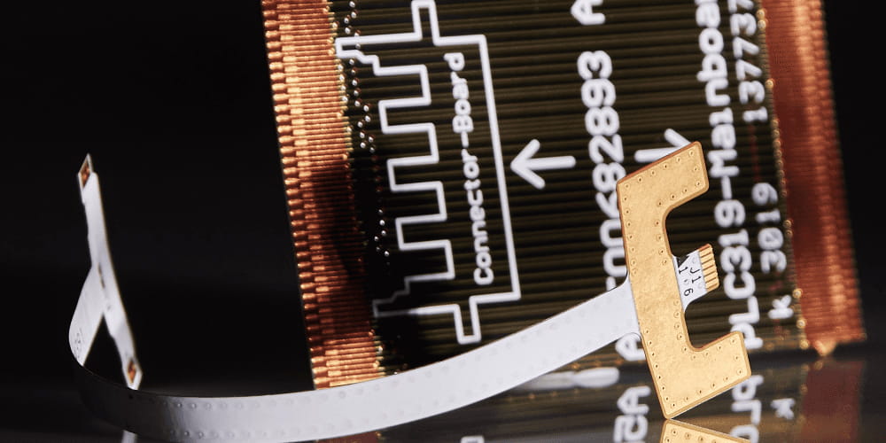
Five years ago, controlled impedance on flex was a specialty request—something you'd see in a satellite program or a high-end medical scope. In 2026, it's everywhere. MIPI CSI-3 running over a folding phone hinge. 5G FR2 modules tucked behind curved antenna carriers. Wearable patches that need 100 Mbps through a 3 mm bend radius. If your signal is fast and your board moves, "flex + impedance" is no longer a nice-to-have. It's the only way the thing works.

The problem is, most teams still treat it like rigid PCB design with a thinner core. It isn't. And the gap between "it simulates fine" and "it passes EMI in a folded state" is where a lot of projects quietly die.

Flex PCB with Controlled Impedance

What Is a Flex PCB with Controlled Impedance?

At its core, it's simple: a flexible circuit where the signal traces are designed to hold a consistent characteristic impedance—50Ω single-ended, 100Ω differential—over their entire length, including bends, transitions, and dynamic flex zones.

In rigid boards, we get away with calling it "controlled" if the trace width is right and the fab holds ±10%. On flex, that definition is incomplete. The trace isn't just sitting on a slab of FR-4. It's on polyimide that bends, above a ground plane that's been cut into a mesh, with a coverlay whose thickness tolerance is wider than most people realize. If any of those move, your 100Ω becomes 87Ω, then 112Ω, then a reflection you can't find because it only shows up when the hinge closes.

Controlled impedance on flex means the whole mechanical stack is part of the transmission line. Not just the copper.

Flex vs. Rigid: Why Impedance Control Is Fundamentally Different

Dimension Rigid PCB Flex PCB
Base material FR-4 (glass + epoxy) Polyimide
Dk 4.0–4.8, varies with glass weave 3.2–3.4, uniform
Dielectric thickness 2–60 mils, easy to dial in 0.5–4 mils, every 0.5 mil hurts bend
Reference plane Solid copper Hatched / cross-hatched
Impedance model Standard microstrip/stripline Standard models fail
Mechanical impact None Bend radius directly shifts impedance
Cost baseline $ 2–4×, depending on test


Material Choices That Actually Matter

Polyimide, Not Because It's Fancy—Because It's Predictable

No glass weave = no Dk hotspots. Cast polyimide holds thickness better than most people expect. 1 mil, 2 mil, 3 mil—it does what it says. That alone makes flex impedance possible.

Adhesive vs. Adhesiveless

Adhesive-based constructions sandwich an acrylic layer between copper and polyimide. Different Dk, different thickness control, and it flows during lamination. For controlled impedance, adhesiveless is the real baseline. Polyimide cast directly onto copper = one fewer variable.

Copper: ED or RA?

ED is fine for static flex. If your design folds 10k+ cycles, RA copper survives better. But both are ½ oz for a reason: thinner is more flexible, but ¼ oz gets fragile and hard to etch cleanly. For impedance work, ½ oz is the sweet spot—stable, repeatable, and bendable enough.

The Coverlay Variable

This one surprises people. Coverlay isn't as tightly controlled as a rigid soldermask. ±1 mil on a 2 mil dielectric is ±25% Dk shift. If your impedance budget is tight, coverlay thickness and registration must be part of the model—not an afterthought.

Stack-Up: What Works, What Breaks

Microstrip (2-layer flex)​

Outer trace, hatched ground below. Best bendability. What most camera ribbons and hinge flexes actually are.

Stripline (4-layer+)​

Trace between two hatched planes. Better shielding, worse bend. We use this when you need 100Ω through a noisy environment and can afford the radius.

Rigid-Flex Transitions​

This is where most designs fail silently. A trace leaves rigid (stripline, solid ground), hits the flex zone (microstrip, hatched), and nobody models the transition. The right way: keep the reference structure as continuous as possible, avoid vias right at the bend, and verify with TDR across the joint. Not just in the flex.

Design Rules That Keep You Out of Trouble

Don't chase thinness blindly.​ A 0.5 mil core gets you flexibility but makes 50Ω almost impossible without ridiculous width. 2 mil is the practical floor for most controlled-impedance flex.
Ask your fab for their hatch data, not their opinion.​ If they can't send you a TDR plot of their 50% fill, 2 mil polyimide stack-up, keep looking.
Simulate, but verify.​ Field solvers get you close. TDR on the actual panel gets you right.
Bend radius is part of SI.​ If your spec says 3 mm bend, test at 2.5 mm and 3.5 mm. Impedance drifts. You want to know which way.
Watch the stiffener edge.​ Where FR-4 or PI stiffener ends, impedance jumps. Taper it, or accept the bump and design margin.

Where This Is Being Used Right Now

High-speed camera modules: MIPI D-PHY/C-PHY over 100Ω differential flex, sometimes 4–6 lanes through a hinge
5G/mmWave front ends: 5–28 GHz routing where polyimide's stable Dk actually beats FR-4
Wearables: Sensor-to-SoC at 1–3 Gbps, body-worn, bending with every motion
Endoscopes & imaging catheters: 400+ Mbps over 2–3 mm diameter flex, sterilizable
ADAS cameras: PPF over flex, under-hood rated, ±5% impedance or the ISP throws errors
Foldables / AR-VR: Dynamic bend + high data. If the hinge moves, the line must hold.

IPC Standards

Standard Real-world meaning
IPC-6013 Your board won't fall apart
IPC-2223 Flex-specific design rules (hatch, bend, etc.)
IPC-TM-650 TDR test method—this is how you prove impedance

How to Evaluate a Flex Controlled Impedance Partner ?

Ask five things:

"Show me TDR data for your 2-mil adhesiveless stack-up with 50% hatch."​
If they say "we use a calculator," they're not your partner.
"What's your tested tolerance on flex?"​
±10% is standard. ±5% means they actually measure.
"Do you model hatch, or use solid-ground formulas?"​
The honest answer tells you everything.
"What happens to my impedance when the flex is bent to 3R?"​
If they shrug, they've never tested it.
"Can I see a recent coupon report from a 100Ω differential job?"​
Redact the customer name. The data should exist.

Share This Story, Choose Your Platform!
Application of related products
Whatsapp: 85292069596
Files (zip or rar files accepted. Max 20MB.)
Link Us on