Web Analytics Made Easy - Statcounter
Rigid Flex PCB Assembly
This website uses cookies:
Our website use cookies to analyze website accesses and improve your online experience. By continuing browsing this website,you agree to our use of cookies and privacy policy.
Accept all cookies
Decline
This website uses cookies:
Our website use cookies to analyze website accesses and improve your online experience. By continuing browsing this website,you agree to our use of cookies and privacy policy.
Accept all cookies
Decline
Get A Quote
Get A Quote
Rigid Flex PCB Assembly
24 July 2026
Views: 30

Rigid Flex PCB Assembly


If you're designing a device that needs to fit into a non-negotiable envelope—think a minimally invasive surgical tool, an ADAS module tucked behind a bumper, or a satellite payload where every cubic centimeter is accounted for—you already know that standard rigid PCBs won't cut it. Rigid Flex PCB Assembly isn't just another PCB variant. It's the enabling technology for three-dimensional electronics, solving the overlapping challenges of space constraints, mechanical reliability, and weight reduction in a single, integrated package.

Rigid Flex PCB Assembly

What is Rigid Flex PCB Assembly?

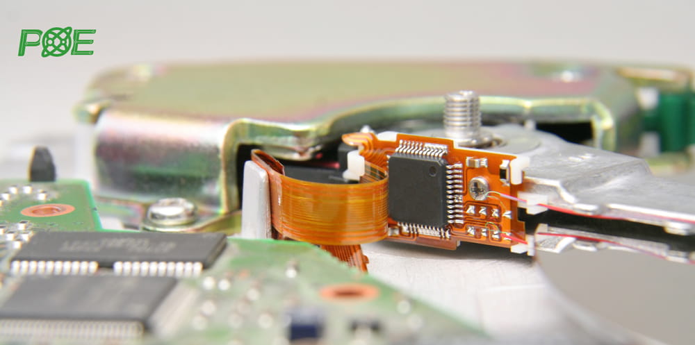
Rigid Flex PCB Assembly is the process of mounting and soldering components onto a hybrid circuit board that permanently integrates rigid FR-4 sections with flexible polyimide circuits.
In practice, this means:

Rigid sections​ provide the structural backbone for component placement, fine-pitch SMT, and mechanical mounting.

Flexible sections​ act as integrated interconnects, allowing the board to bend, fold, and twist to conform to the product's housing.

The strategic advantage here is the elimination of discrete connectors, wiring harnesses, and board-to-board interfaces. You aren't just buying a board; you're buying a reduction in failure points and a gain in volumetric efficiency.

The Rigid Flex Assembly Process

Phase 1: Material Preparation and Conditioning

Polyimide is hygroscopic; it readily absorbs atmospheric moisture. During reflow at 240°C–260°C, trapped moisture vaporizes instantly. Without proper mitigation, this causes delamination or the "popcorn effect."

We enforce strict pre-baking cycles (100°C–120°C) immediately prior to SMT to drive off moisture. Skipping this step is a common industry shortcut that leads to latent field failures.

Phase 2: Fixturing and Support

A flopping flex circuit cannot maintain coplanarity on a standard conveyor.

We utilize custom rigid carriers and precision fixtures to immobilize the flexible sections, ensuring flatness during paste printing and pick-and-place.

Phase 3: Design for Assembly (DFA) Review

The Transition Zone—where rigid FR-4 meets flexible polyimide—is the most mechanically stressed area of the board.

We look for vias placed too close to the bend line, inadequate teardrops on pads, and insufficient stiffener support. We ensure components near flex areas have mechanical backing to prevent pad lifting during flexing.

Phase 4: SMT Assembly with Specialized Controls

Placement:​ Components are strictly limited to rigid sections. Placing parts on flex creates stress risers that will fail under cyclic loading.

Reflow:​ We utilize modified reflow profiles—often slightly longer preheat phases—to accommodate the different thermal masses and heat dissipation characteristics of polyimide versus FR-4.

Phase 5: Inspection and Testing

AOI:​ 100% inspection for solder joint quality.

X-ray:​ Critical for BGAs and QFNs on the rigid sections.

Electrical Testing:​ Continuity and isolation testing per IPC-9252.

Industries That Rely on Rigid Flex PCB Assembly

Medical Devices:​ We have supported programs involving implantable neurostimulators and minimally invasive surgical tools. Here, ISO 13485:2016​ compliance isn't just a certificate; it's a requirement for traceability and biocompatibility.

Automotive Electronics:​ ADAS cameras and LiDAR modules require tolerance to -40°C to 105°C thermal shocks.

Wearables:​ High-density interconnects (HDI) rigid flex allows fitness trackers to wrap around a wrist without bulky connectors.

Industrial IoT:​ Sensor nodes deployed in harsh environments where connector corrosion is a known failure mode.

How to Choose a Rigid Flex PCB Assembly Partner

Technical Depth:​ Do they understand bend radius calculations and stiffener integration? Ask them about their DFM process for the transition zone.

Certifications:​ Verify ISO 9001:2015, ISO 13485:2016, IPC-A-610 Class 3, and J-STD-001​ compliance. For medical and automotive, this is table stakes.

Supply Chain Stability:​ Polyimide laminates can face allocation. Does your partner have strategic inventory or multi-source agreements?

Quality Systems:​ Look for RoHS​ and REACH​ compliance, and ensure they have UL Certification. More importantly, ask how they handle material traceability for Class 3 assemblies.

Why POE for Your Rigid Flex PCB Assembly

At POE, we treat rigid flex not as a specialty item, but as a core competency. Our approach is built on three pillars: Process Control, Engineering Partnership, and Supply Chain Integrity.

Process Control:​ We don't skip pre-baking. We don't guess on reflow profiles. Our IPC-certified operators follow documented procedures that align with IPC-A-610 Class 3​ workmanship standards.

Engineering Partnership:​ We conduct a rigorous DFA review before any material is cut. We've seen too many designs where a via was placed one millimeter too close to a bend line—a mistake that costs thousands once the boards are fabricated. We catch those errors in the Gerber review.

Supply Chain Integrity:​ Holding ISO 13485:2016​ and ISO 9001:2015​ certifications, we manage a qualified supply chain for polyimide materials, ensuring that your production run doesn't stall due to material shortages.

Compliance:​ Our assemblies meet IPC J-STD-001, RoHS, REACH, and UL​ requirements, ensuring global market access.

We have supported complex rigid flex builds for medical wearables and automotive sensor modules—projects where failure was not an option. We understand that the "cheapest" bid often becomes the most expensive when you factor in field returns.

FAQ

Q: What is the minimum bend radius for rigid flex?

A: It depends on the layer count and copper weight. For static applications, we typically recommend a minimum bend radius of 6 to 10 times the thickness of the flex layer. For dynamic bending (flex-to-install), it can be higher. We verify this during DFM.

Q: Can components be mounted on the flexible section?

A: Generally, no. Solder joints on flex are prone to cracking under stress. Components should be mounted on rigid sections or on stiffeners. Placing components directly on flex is a common design flaw we flag early.

Q: Why is pre-baking so critical?

A: Polyimide absorbs moisture. If not baked out, this moisture turns to steam during reflow, causing internal delamination. It's a simple step that is surprisingly overlooked in low-cost assembly houses.

Q: What IPC standards apply?

A: Key standards include IPC-6013​ (Qualification for Flex/Rigid-Flex), IPC-6012​ (Rigid sections), IPC-A-610 Class 3​ (Acceptability), and IPC-2223​ (Design).

Q: How long does it take?

A: Expect lead times to be 30–50% longer than standard rigid PCBs due to the sequential lamination and handling requirements. We provide detailed schedules during quoting.

Ready to Start Your Rigid Flex PCB Assembly Project?

If you're evaluating rigid flex, the most expensive mistake you can make is discovering a design flaw after fabrication.

Send us your design files (Gerbers, BOM, and stack-up details). We'll perform a comprehensive DFM/DFA review focused specifically on rigid-flex transition zones, bend radius validation, and material selection. Within 24 hours, you'll receive a fixed-price quote and a technical assessment that outlines the risks and opportunities in your design.

Let's build something that lasts. Contact POE today.

Share This Story, Choose Your Platform!
Application of related products
Whatsapp: 85292069596
Files (zip or rar files accepted. Max 20MB.)
Link Us on