China Fine Pitch PCB Assembly
China Fine Pitch PCB Assembly
If you're designing anything that actually matters in 2026—AI accelerators, 5G RF front ends, ADAS domain controllers, flagship phone motherboards—you've already hit the same wall: the packages are smaller, the pitches are tighter, and "standard SMT" doesn't cut it anymore.
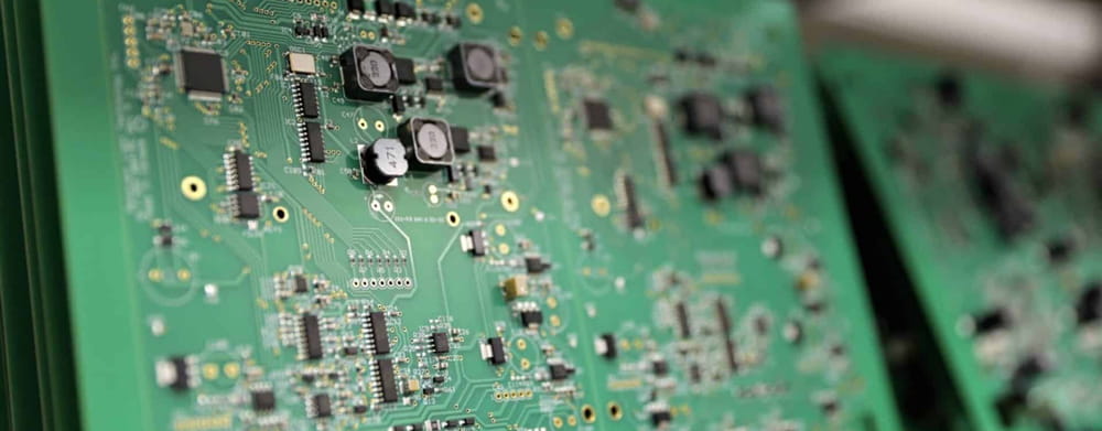
What "Fine Pitch" Actually Means
In assembly terms, fine pitch starts at 0.4 mm lead spacing and below:
Fine-pitch BGAs: 0.4 mm / 0.35 mm / 0.3 mm
Fine-pitch QFNs: 0.4 mm and occasionally 0.35 mm
01005 and 0201 passives (always paired with tight-pitch ICs)
The shorthand we use on the floor:
Standard pitch: ≥0.65 mm — conventional SMT, ±50–100 µm placement
Fine pitch: ≤0.4 mm — ±30–40 µm, laser stencil, AOI + X-ray
Ultra-fine: ≤0.35 mm — ±25 µm, 3D SPI/X-ray, vacuum reflow, HDI mandatory
Fine Pitch vs. Standard
Most delays happen because people think fine pitch is the same process with tighter numbers. It isn't.
At 0.3 mm pitch, the pad gap is thinner than a human hair. The stencil aperture tolerance drops from ±15 µm to ±3–5 µm. Inspection jumps from AOI-only to 3D X-ray. First-pass yield drops 3–5 points. And the cost? Two to five times higher—because you're paying for a different process stack, not just "precision."
Where Fine Pitch Actually Fails
1. Placement: 25 Microns Is Not a Slogan
At 0.3 mm pitch, pad diameter is ~0.20 mm. A 50 µm shift is 17% of your margin gone. After reflow, that's a short or a head-in-pillow.
On our lines, 0.3 mm BGA is locked at ±25 µm. Anything looser is a coin toss. "High-precision mode" on a 2017 pick-and-place doesn't count.
2. Printing Is the Real Boss
Most fine pitch scrap is born at the printer.
±3–5 µm aperture tolerance (laser-cut, polished).
Stepped stencil: 0.08–0.10 mm in fine-pitch zones.
3D SPI on every board: volume, height, area—not just coupons.
Too much paste = bridge. Too little = open. We've seen "standard" 0.4 mm stencils at ±12 µm—fine for 0.65 mm, fatal for 0.35 mm.
3. Reflow: Warpage and Voids
Fine-pitch BGAs don't like heat, and they don't like gas.
Warpage creates head-in-pillow: ball and pad never touch.
Trapped flux = voids—this isn't cosmetic, it's reliability.
Vacuum reflow helps. With a dialed process, we see 8–12% void rates (IPC-7095) on 0.3–0.4 mm BGAs. Some "perfect" builds hit 5%. Messy layouts sit at 15% and need a stencil rev. Anyone quoting "<3% always" is cherry-picking.
4. Inspection: AOI Can't See the Bottom
AOI: bridges, offset, top-side opens.
X-ray: BGA voids, hidden shorts, head-in-pillow.
Cross-section: for new projects and failure analysis.
X-ray is common in China now. Reading it isn't. An engineer who knows slice views is worth more than the machine.
Who's Actually Running 0.3–0.4 mm in 2026?
AI edge / inference: 0.4 mm BGA, 12–16 layer HDI, thick power.
5G/6G RF: tight pitch, microvias under every ground pad.
ADAS: 0.35 mm BGA, AEC-Q100, 3D X-ray per board.
Flagship phones/wearables: 01005 + 0.3 mm AP BGA, stacked HDI.
Medical imaging: FPGA @ 0.4 mm, full traceability, 100% X-ray
If your product isn't here, you may not need ultra-fine. If it is, you don't have a choice.
How to Vet a Fine Pitch Supplier?
"What's your placement tolerance on 0.3 mm BGA?"
Good: ±25 µm with CPK. Red flag: "very accurate."
"Show me your SPI and X-ray workflow."
Good: 3D SPI every board + 3D X-ray on every BGA lot.
"What's your void range on 0.35 mm BGA?"
Honest: 8–12%. Too perfect: "under 3% guaranteed."
What POE Does Differently?
0.3 mm BGA + 01005 qualified; 0.25 mm on request
±25 µm placement, laser stencil ±3–5 µm
SPI + AOI + X-ray on every build
Qualified HDI supply chain—via-in-pad specs written by POE, not default fab
Turnkey: PCB sourcing + DFM + assembly + test
IPC-A-610 Class 2/3, ISO 13485
DFM feedback in 24h, in plain English, with reasons
We don't make the board. We own the joint. That's where your 0.3 mm BGA lives or dies.
Quick Answers
Is 0.35 mm ultra-fine? Yes. Needs ±25 µm and X-ray.
0.4 mm BGA on 4-layer FR-4? Technically yes. Practically painful—expect EMI and fanout fights.
Why 15% voids? Usually aperture + open via + profile. Fixed by shrinking aperture and capping the via.
Prototype lead time? 3–5 days with inspection. 24h rush means something skipped.
Cost multiple? 2–3× at 0.4 mm, 3–5× at 0.3 mm. It's yield risk, not labor.

 Email: all@poe-pcba.com
 Whatsapp: 85292069596
 Tel: 0755-25312250/ +8613798543496
 Factory Address: Floor 3, Jinyuan Industrial Park, No. 56, Tangtou Avenue, Shiyan Town, Baoan District, Shenzhen China





