Quality Control

Importance of Quality Control and the role it plays in ensuring product reliability.l In Surface Mount Technology (SMT) manufacturing, quality inspection is the guard of proper functionality of electronic products. Each stage of SMT production, from paste printing to the final assembly, is with potential errors that can severely impact a product's performance. This proactive approach ensures that the end - product functions as intended, meeting the required electrical and performance specifications. Also, it can improve the production efficiency and lower down costl due to rework on the defective PCBA boards.
Quality control processes and measures
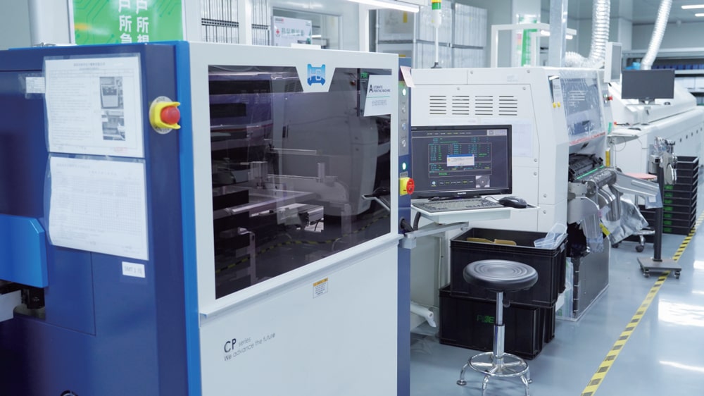
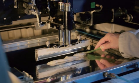
Paste Printing Inspection
Solder paste printing inspection ensures that the volume, position, and shape of the solder paste on PCB pads meet specifications, which directly affects the soldering quality of subsequent components.
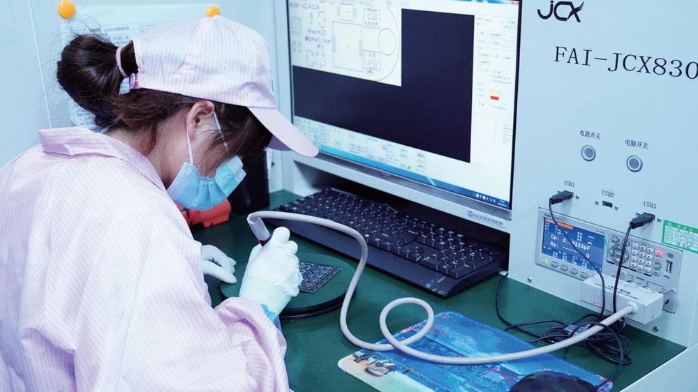
FAI
FAl refers First Article Inspection, it allows simple inspection of the first board, which is particularly important for volume production. First article inspection can fulfill the process validation requirement of a quality management system such as ISO9001: 2015.
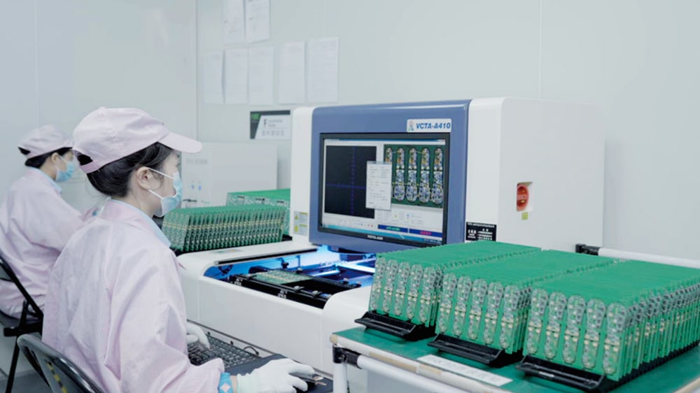
AOI
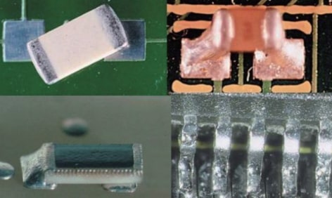
AOI equipment takes high-resolution photos of PCBA through an optical system composed of a camera and a light source. These images are transmitted to a computer system for analysis and comparison through image processing algorithms. AOI test can be applied to detect a lot of surface defects including scratches, nodules, stains, opens, shorts, insufficient or excessive solder, incorrect components, missing components, incorrect polarity of components etc.
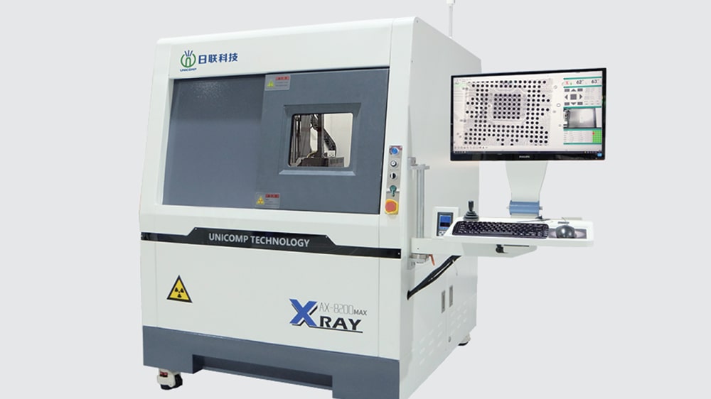
X-Ray Inspection for SMT Assembly
To use X-ray light machine to detect the quality of welding especially for products have BGA, FBGA, QFN, or small parts like 0201 package. As AOI can not see through to detect the bottom of the solder ball welding, while X-ray see through to detect whether its false welding, empty welding and other issues. Also PCBA used for such as Automotive electronics, avionics, high precision medical electronics and other high-end industries will have X-ray testing demand.
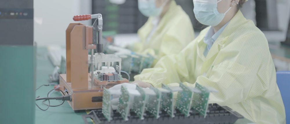
Functional Testing
Functional testing is a crucial quality control process in the electronics manufacturing industry. This type of testing is designed to verify that the assembled PCBA board operates as intended, meeting all the specified functional requirements. Usually the customers will send POE testing instruction including material shall be prepared and testing procedures, tips ect. POE can custom testing Jig specifically for the boards and conduct full test and make sure 100% pass test before shipping.
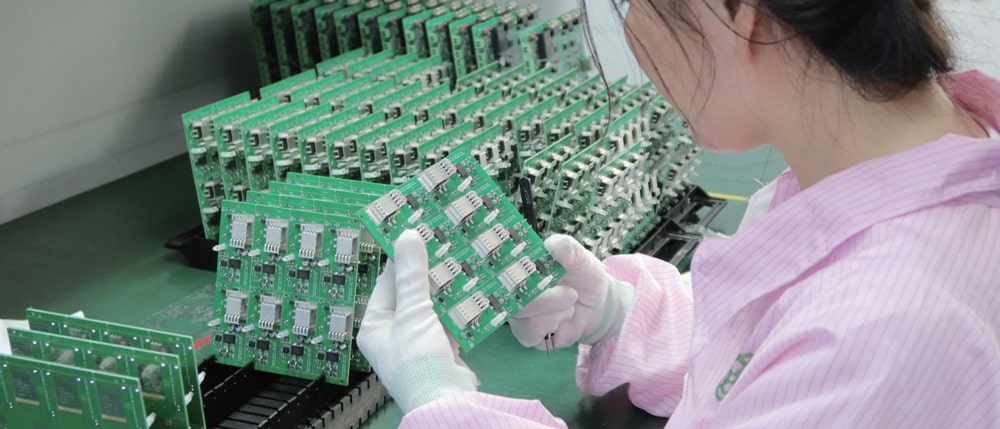
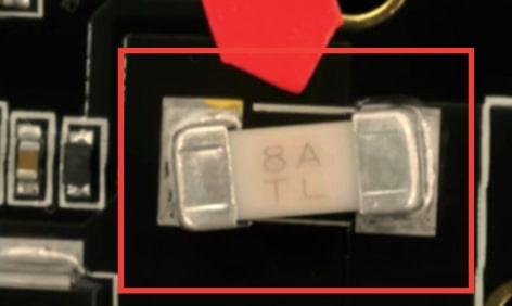
Visual Inspection
Manual visual inspection offers high flexibility, adapting to small-batch or customized production; low cost, requiring no expensive equipment; greater accuracy for complex or irregularly shaped components; the ability to handle multiple defect types (e.g., cosmetic flaws); real-time adjustment of standards to accommodate design changes; and the capability to identify potential issues beyond existing defects.
Common issues in PCBA and solution
POE is conducting and following the methods strictly to avoid any possible issues.
1.Poor Paste Printing
Common Problems:
| Excessive or Insufficient Paste Volume: Too much solder paste may lead to short circuits, while too little may cause soldering defects. |
 |
| Paste Offset: Causes poor contact between component pins and solder pads, thereby affecting soldering quality. |
 |
| Paste Bridging: The connection of solder paste between adjacent pads, resulting in an electrical short circuit. |
 |
Avoidance Methods:
Regularly Maintain Printing Equipment: Clean and calibrate the steel mesh to ensure accurate opening dimensions and prevent blockages. For instance, conduct a comprehensive cleaning of the steel mesh once a week and perform an opening size inspection monthly.
Optimize Printing Parameters: Adjust parameters such as printing speed, pressure, and squeegee angle. Generally speaking, the printing speed is controlled at 30-60mm/s, the printing pressure is adjusted according to the thickness of the PCB and the type of steel mesh, and the squeegee angle is maintained at 45-60°.
Use High-Quality Solder Paste: Select solder paste that meets the required standards, and pay attention to its storage conditions and shelf life. The solder paste should be stored in an environment with a temperature range of 2-10C, and it needs to be warmed up to room temperature before use.
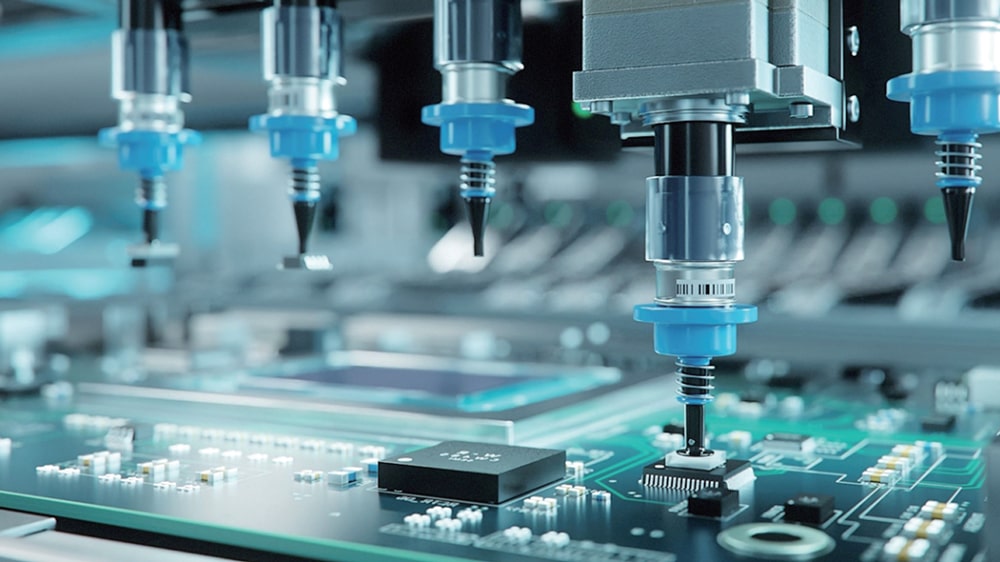
2.Component Mounting Errors
Common Problems:
| Wrong Component Type: Using the wrong component can cause abnormal circuit functionality. |
 |
| Wrong Component Orientation: Incorrect orientation of polarized components can cause them to malfunction or even become damaged. |
 |
| Component Mounting Offset: It affects the soldering effect and may cause virtual soldering or open circuits. |
 |
Avoidance Methods:
Strengthen Material Management: Strictly follow the BOM for material requisition, label components and store them in different areas to prevent confusion. Conduct a secondary verification before the materials are used in production.
Optimize Mounter Program: Ensure the accuracy of the coordinate data for the mounter and perform regular calibrations. Whenever the component model or PCB version is changed, the program must be rechecked and optimized.
Add Error proofing devices: Such as installing a vision system on a surface mount machine to perform real-time detection and correction of component model, orientation, and position.
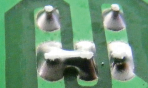
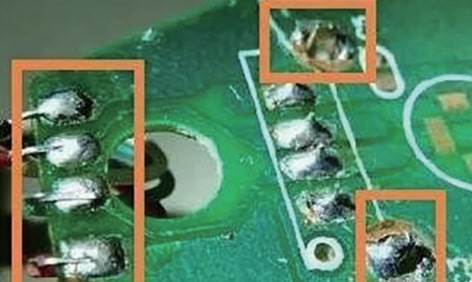
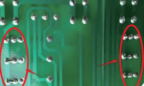
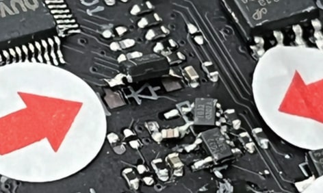
3.Soldering Defects
| Common Problems: Cold Solder Joint: The connection between the solder joint and the component pin or pad is not firm, and the circuit may experience intermittent conduction. |
 |
| Short Circuit: An electrical short circuit caused by the solder connection between adjacent solder joints. |
 |
| Tombstoning: One end of the chip component is raised in a tombstone shape, resulting in poor electrical connections. |
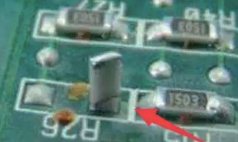 |
Avoidance Methods: Optimize Reflow Soldering Profile: Adjust the temperature and time of preheating, heating, reflow, and cooling stages according to different components and PCB materials. For example, for lead-free soldering, the preheating temperature is generally between 150-180°C and the time is 60-120 seconds; The peak reflux temperature is between 235-250°C for 10-30 seconds.
Control Welding Environment: Maintain stable temperature and humidity in the workshop, with temperature controlled between 22-28°C and humidity controlled between 40%-60%
Enhance the Solderability of Components and PCBs: Pre-treat component pins and PCB pads to remove oxide layers.
4.Appearance Defects
Common Problems:
| Component Damage: Damage to components caused by external impact during transportation and installation. |
 |
| PCB Scratch: Scratches caused by friction between the PCB and equipment, tools, etc. during the production process. |
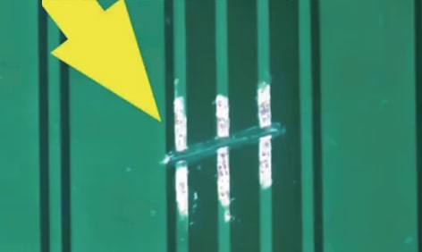 |
| Unclear Labeling: The silk screen label is blurry or incomplete, which affects subsequent maintenance and testing. |
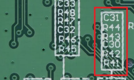 |
Avoidance Methods:
Optimize Production Process: During the transportation and installation of components, use appropriate fixtures and jigs to avoid excessive external forces on the components.
Strengthen Equipment and Tool Management: Regularly inspect and maintain production equipment to ensure smooth surfaces and no sharp edges. Regularly clean and replace production tools to prevent them from scratching the PCB.
Improve Screen Printing Quality: Select appropriate screen printing ink and screen, adjust screen printing parameters to ensure clear and complete labeling. Regularly calibrate and maintain screen printing equipment.
In conclusion, by understanding these common issues and their solutions, POE can enhance PCBA quality, streamline production, and boost competitiveness in the electronics industry.
Moreover, by strictly adhering to quality standards, POE can avoid potential legal issues and regulatory non - compliance, ensuring seamless market access on a global scale. The data gleaned from quality inspections serves as a compass for process improvement, enabling manufacturers to optimize production, reduce waste, and increase overall efficiency. In the highly competitive electronics landscape, SMT quality is the differentiator that sets apart industry leaders from the rest. It is a commitment to excellence that not only benefits the manufacturer but also enriches the end - user experience. As technology continues to evolve, upholding SMT quality remains an unwavering imperative for sustainable growth and success in the electronics industry.

 Email: all@poe-pcba.com
 Whatsapp: 85292069596
 Tel: 0755-25312250/ +8613798543496
 Factory Address: Floor 3, Jinyuan Industrial Park, No. 56, Tangtou Avenue, Shiyan Town, Baoan District, Shenzhen China


